# Rotated RCNN
论文:Oriented R-CNN for Object Detection (opens new window)
代码:OBBDetection (opens new window)
西北工业大学的Xingxing Xie等于2021年08月提交到ICCV 2021的论文
# 0.基础介绍
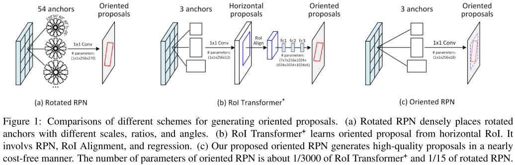
与水平检测框不同,旋转检测框会给出对象的minAreaRect,是带角度的物体检测框。结合水平检测框的方法,旋转框检测常用的方法有以下几种。Rotated Region Proposal Network,参考Faster RCNN中提出的RPN,Rotated RPN在每个特征图上使用3种scale,3种ratio,6种angle共计54个锚框。这种方法可以提高对象检测的召回率,但是因引入过多的anchor,譬如在80x80x54的特征图上会生成345600个候选框,会导致占用过多的内存和推理时间。RoI Transformer使用RPN, RoI Alignment and regression来生成Oriented Proposals,这种方法相比Rotated RPN减少了参数量,但依然存在额外的计算量。Oriented RPN,本文提出的方法,使用本文提出的中点偏移Midpoint Offset旋转框表示法,将RPN输出Proposals的位置回归分支由4个变量改成6个变量来生成候选框,相比前两种方法,该方法使用全卷积的RPN,具有更少的运算量。
# 1.旋转框的中点偏移表示法


通过这种表示方式,巧妙的将角度问题表示成了距离,可以使用IoU计算的不可导和角度表示时的边界问题。
# 2.Oriented R-CNN架构

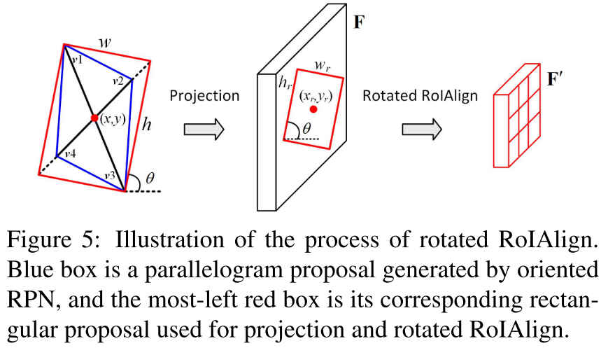
Oriented R-CNN的整体架构如上图,与Faster R-CNN中的结构基本一样,除了RPN结构位置回归分支输出的回归变量由4个Oriented Proposals。在检测头部分根据proposals做RoI Alignment时,因Oriented RPN生成的是旋转的候选框,因此做RoI Align时,需要先对RoI做旋转,因此称之为RotatedRoIAlign。
# 2.1 Oriented RPN
Oriented RPN中使用的仍然是水平anchor,每层特征图上共3个,宽高比分别为anchor的面积分别为
每个anchor使用四维向量表示:
其中
Oriented RPN的输出是proposals相对于anchor的偏移量,
再通过以下公式对回归得到的偏移量解码即可得到proposals:
如旋转框的中点偏移表示法图中所示,公式中的proposal的中心,
既然Oriented RPN的回归分支输出的是bounding box位置的偏移量,因此在网络的训练过程中需要先将输入对应的ground truth box和proposal完成匹配(可以多个proposal对应1个gt box),然后还需要将proposal和对应的gt box编码成偏移量的形式
其中,
在以上的介绍中,有两个地方值的注意。一个是label assignment中,是先求ground truth oriented box的外接矩形,然后计算水平anchor和外接矩形的IoU来实现标签匹配的,所以标签匹配依靠的仍然是水平检测框之间的IoU。可以参考MMROTATE (opens new window)中的代码实现:
# mmrotate/models/dense_heads/oriented_rpn_head.py
# line 75-81
gt_hbboxes = obb2xyxy(gt_bboxes, self.version)
assign_result = self.assigner.assign(anchors, gt_hbboxes, gt_bboxes_ignore, None if self.sampling else gt_labels)
sampling_result = self.sampler.sample(assign_result, anchors, gt_hbboxes)
另外一点是,Oriented RPN训练中使用的损失函数,分类使用的交叉熵,回归分支使用的SmoothL1Loss。
# configs/oriented_rcnn/oriented_rcnn_r50_fpn_1x_dota_le90.py
loss_cls=dict(type='CrossEntropyLoss', use_sigmoid=True, loss_weight=1.0),
loss_bbox=dict(type='SmoothL1Loss', beta=0.1111111111111111, loss_weight=1.0)
# 2.2 Rotated RoI Alignment
本篇文章另外一部分工作主要就在拿到proposals后对RoI的对齐池化上。
Faster R-CNN中使用的RPN和Mask R-CNN中提出的RoIAlign的介绍可以参考:(六) Region Proposal Network (opens new window)和(五)ROI Pooling 与 ROI Align (opens new window)。
而Oriented RPN给出的proposal是带角度的外接矩形,这和水平框的不太一样,要想对Oriented RoI做Alignment,需要先将Orientd RoI做一个旋转,然后就可以按照水平的常规RoI来处理了,这就是RotateRoIAlign的全部,如下图所示:
这里有一点需要注意,通过回归
关于RotatedRoIAlign的实现可以参考官方仓库,
template <typename T>
void pre_calc_for_bilinear_interpolate(
    const int height,
    const int width,
    const int pooled_height,
    const int pooled_width,
    const int iy_upper,
    const int ix_upper,
    T roi_start_h,
    T roi_start_w,
    T bin_size_h,
    T bin_size_w,
    int roi_bin_grid_h,
    int roi_bin_grid_w,
    T roi_center_h,
    T roi_center_w,
    T cos_theta,
    T sin_theta,
    std::vector<PreCalc<T>>& pre_calc) {
  int pre_calc_index = 0;
  for (int ph = 0; ph < pooled_height; ph++) {
    for (int pw = 0; pw < pooled_width; pw++) {
      for (int iy = 0; iy < iy_upper; iy++) {
        const T yy = roi_start_h + ph * bin_size_h +
            static_cast<T>(iy + .5f) * bin_size_h /
                static_cast<T>(roi_bin_grid_h); // e.g., 0.5, 1.5
        for (int ix = 0; ix < ix_upper; ix++) {
          const T xx = roi_start_w + pw * bin_size_w +
              static_cast<T>(ix + .5f) * bin_size_w /
                  static_cast<T>(roi_bin_grid_w);

          // Rotate by theta around the center and translate
          // In image space, (y, x) is the order for Right Handed System,
          // and this is essentially multiplying the point by a rotation matrix
          // to rotate it counterclockwise through angle theta.
          T y = yy * cos_theta - xx * sin_theta + roi_center_h;
          T x = yy * sin_theta + xx * cos_theta + roi_center_w;
          // deal with: inverse elements are out of feature map boundary
          if (y < -1.0 || y > height || x < -1.0 || x > width) {
            // empty
            PreCalc<T> pc;
            pc.pos1 = 0;
            pc.pos2 = 0;
            pc.pos3 = 0;
            pc.pos4 = 0;
            pc.w1 = 0;
            pc.w2 = 0;
            pc.w3 = 0;
            pc.w4 = 0;
            pre_calc[pre_calc_index] = pc;
            pre_calc_index += 1;
            continue;
          }

          if (y < 0) {
            y = 0;
          }
          if (x < 0) {
            x = 0;
          }

          int y_low = (int)y;
          int x_low = (int)x;
          int y_high;
          int x_high;

          if (y_low >= height - 1) {
            y_high = y_low = height - 1;
            y = (T)y_low;
          } else {
            y_high = y_low + 1;
          }

          if (x_low >= width - 1) {
            x_high = x_low = width - 1;
            x = (T)x_low;
          } else {
            x_high = x_low + 1;
          }

          T ly = y - y_low;
          T lx = x - x_low;
          T hy = 1. - ly, hx = 1. - lx;
          T w1 = hy * hx, w2 = hy * lx, w3 = ly * hx, w4 = ly * lx;

          // save weights and indices
          PreCalc<T> pc;
          pc.pos1 = y_low * width + x_low;
          pc.pos2 = y_low * width + x_high;
          pc.pos3 = y_high * width + x_low;
          pc.pos4 = y_high * width + x_high;
          pc.w1 = w1;
          pc.w2 = w2;
          pc.w3 = w3;
          pc.w4 = w4;
          pre_calc[pre_calc_index] = pc;

          pre_calc_index += 1;
        }
      }
    }
  }
}